rpk2 doc
all rpk2 info in this page
Table of contents
- Firmware files
- Tools for rpk2
- basics
- TS3USB221 USB Switch and poweroff
- bootloaders
- replace flash and bootloaders via JTAG and ICSP
- How to program ATMEGA32U4 and AT90USB1287 using Microchip Atmel Studio + USBasp-clone
- How to program and debug ATMEGA32U4 and AT90USB1287 via JTAG using Microchip Atmel Studio + ATMEL ICE
- How to program ATMEGA32U4 using Arduino IDE + printer bootloader
- How to port the previous Arduino Sketch project to Microchip Atmel Studio (better IDE with JTAG Debugging)
- How to program AT90USB1287 using Arduino IDE + teensyduino + printer bootloader
- How to port the previous Teensy Arduino Sketch project to Microchip Atmel Studio (better IDE with JTAG Debugging)
- demo firmware
- at90audioinput
- at90audiooutput
- at90dualmidi
- at90dualvirtualserial
- at90ethernet
- at90generichid
- at90keyboard
- at90keyboardmouse
- at90keyboardmousenomulti
- at90midi
- at90mouse
- at90virtualserial
- at90masskeyboardfatfs - at90masskeyboard2gbsd - at90masskeyboardvirtualserialfatfs - at90masskeyboardvirtualserial2gbsd
- at90extmem
- at90readwritespisd
- at90serialhello
- at90softuartx
- at90swuart
- at90timers
- at90buttons
- at90blink
- at90sketchbasicexample
- leoaltsoftserial
- leoblink
- leobuttons
- leohellowkeyboard
- leorfrecver
- leosketchbasicexample
- leousbswitchtoat90
- leoencchat
- leowinbondflashdriver
- adafruit_feather_32u4 demos
- evilmass
- ATMEGA32U4 fuses
- AT90USB1297 fuses
- schematics (MIT LICENSE)
- PCB (MIT LICENSE)
- BOM
Firmware files
All firmware (.hex and .elf files) + code: https://github.com/therealdreg/rpk2
Tools for rpk2
https://github.com/therealdreg/rpk2/releases/download/tools_rpk2/tools_rpk2.zip
Tools for rpk2 includes:
- arduino_modified_rpk2:
- atmel-studio-as-installer-7.0.2397-full: Microchip Atmel Studio
- zadig-2.6: application that installs generic USB drivers, such as WinUSB, libusb-win32/libusb0.sys or libusbK, to help you access USB devices
- Flip Installer 3.4.7.112: Flip supports in-system programming of flash devices through RS232, USB or CAN
- JRE Flip Installer 3.4.7.112: Flip with Java Run-time Environment (JRE) integrated
- flip_linux_3-2-1: Flip for Linux
basics
rpk2 have a TS3USB221 USB switch + two USB chips inside: ATMEGA32U4 and AT90USB1287
rpk2 USB code is powered by LUFA (thx to Dean Camera), so we can offer you various types of bootloaders and demos
both chips can be programmed via bootloader/ICSP/JTAG
Arduino IDE (including libs) and Microchip Atmel Studio are supported
both chips can be debugged via JTAG in Microchip Atmel Studio (including Arduino projects)
So, YES, you can code and debug your firmware like your C projects in Visual Studio!
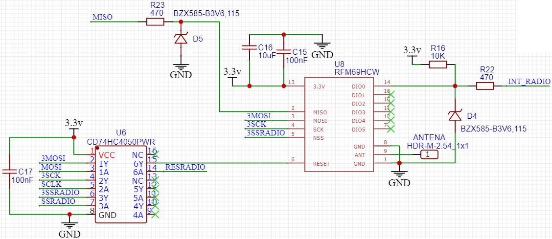
ATMEGA32U4 have connected a RFM69HCW 433MHz module:
- SX1231 based module with SPI interface
- Packet radio with ready-to-go Arduino libraries
- +13 to +20 dBm up to 100 mW Power Output Capability (power output selectable in software)
- 50mA (+13 dBm) to 150mA (+20dBm) current draw for transmissions
- Range of approx. 350 meters, depending on obstructions, frequency, antenna and power output
- Create multipoint networks with individual node addresses
- Encrypted packet engine with AES-128
AT90USB1287 have connected a microSD card reader. AT90USB1287 can poweroff and poweron card reader as needed
AT90USB1287 have connected an external 512Kb RAM AS7C4096A-12TCN
ATMEGA32U4 can poweroff and poweron AT90USB1287 chip as needed
TS3USB221 USB Switch and poweroff
There is only one USB connection, but you can switch between chips as needed (without physical reconnection).
rpk2 have inside a TS3USB221 USB SWITCH chip, this chip is controlled by ATMEGA32U4. So, ATMEGA32U4 can switch USB connection between AT90USB1287 and itself.
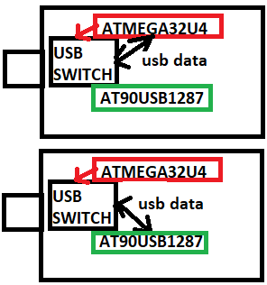
By default, the USB connection is connected to ATMEGA32U4.
If you want use AT90USB1287 via USB (bootloader or flash), first you must flash a program in ATMEGA32U4. Example of USB SWITCH: leousbswitchtoat90.hex
AT90USB1287 and ATMEGA32U4 are connected via UART. So, AT90USB1287 can request to ATMEGA32U4 a msg like:
- “hey, give me the USB connection”
- “I’m done, remove me from the usb connection”
- “please, power off me”
bootloaders
Microcontrollers are usually programmed through a programmer unless you have a piece of firmware in your microcontroller that allows installing new firmware without the need of an external programmer. This is called a bootloader
If you want to use the full program space (flash) of the chip or avoid the bootloader delay, you can program rpk2 using an external programmer like ATMEL ICE (ICSP + JTAG) or USBasp (ICSP)
each rpk2 board has pre-programmed a default bootloader for each chip
at90 / leo - bootloaderprinter (default bootloader for both chips)
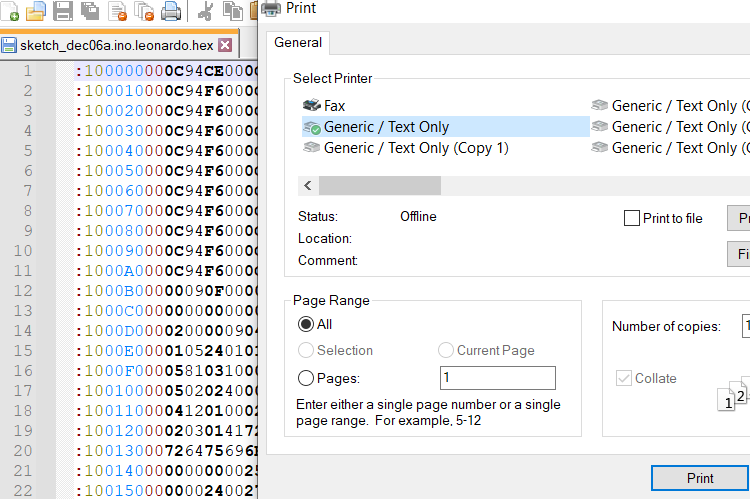
When you connect a default rpk2 board in bootloader mode via USB is detected as a new Generic Text Only Printer.
This printer is capable of reading and parsing “printed” plain-text Intel HEX files to load firmware onto the AVR
Just open a .hex file with Notepad and print it.
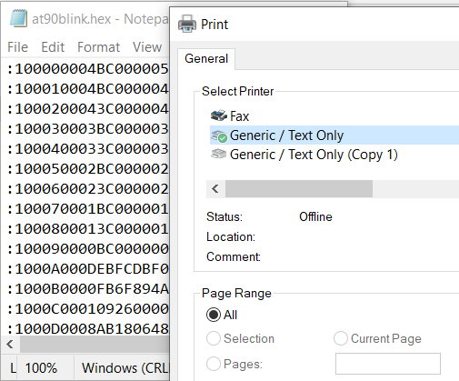
Now you have the chip programmed with the new firmware. Very easy.
How to activate ATMEGA32U4 bootloader:
- press LEO reset button
How to activate AT90USB1287 bootloader:
- you must flash leousbswitchtoat90.hex to ATMEGA32U4
- reconnect rpk2 board
- press AT90 reset + AT90 boot button at same time
- stop pressing reset button
- wait a little and stop pressing AT90 boot button
at90 / leo - bootloadercdcavr109dude
This bootloader enumerates to the host as a CDC Class device (virtual serial port), allowing for AVR109 protocol compatible programming software to load firmware onto the AVR.
How to program leoblink.hex in ATMEGA32U4 (COM16):
- press LEO reset button
- open a cmd.exe
- use avrdude.exe:
"C:\arduino\hardware\tools\avr\bin\avrdude.exe" -v -v -v -C "C:\arduino\hardware\tools\avr\etc\avrdude.conf" -c AVR109 -p atmega32u4 -P COM16 -U flash:w:"leoblink.hex":i -v -v
How to program at90blink.hex in AT90USB1287 (COM16):
- you must flash leousbswitchtoat90.hex to ATMEGA32U4
- reconnect rpk2 board
- press AT90 reset + AT90 boot button at same time
- stop pressing reset button
- wait a little and stop pressing AT90 boot button
- open a cmd.exe
- use avrdude.exe:
"C:\arduino\hardware\tools\avr\bin\avrdude.exe" -v -v -v -C "C:\arduino\hardware\tools\avr\etc\avrdude.conf" -c AVR109 -p at90usb1287 -P COM16 -U flash:w:"at90blink.hex":i -v -v
How to know what COM port use??, just type in cmd.exe:
wmic path Win32_SerialPort get /value

wmic path Win32_SerialPort  where "PNPDeviceID like '%6969%'" get /value
After running this bootloader for the first time on a new computer, may you will need to supply the .INF file located in this demo project’s directory as the device’s driver when running under Windows.
This will enable Windows to use its inbuilt CDC drivers, negating the need for custom drivers for the device.
Other Operating Systems should automatically use their own inbuilt CDC-ACM drivers.
at90 / leo - at90bootloaderdfu
DFU Class device, allowing for DFU-compatible programming software to load firmware onto the AVR.
It spoofs Atmel’s DFU Bootloader USB VID and PID so that the Atmel DFU bootloader drivers included with FLIP will work.
This bootloader is compatible with Atmel’s FLIP utility on Windows machines, and dfu-programmer on Linux machines.
FLIP (Flexible In-System Programmer) is a utility written by Atmel.
The FLIP utility is designed to assist in the bootloader programming of a range of Atmel devices, through several popular physical interfaces including USB.
dfu-programmer is an open-source command line solution for the bootloader programming of Atmel devices through a USB connection, using the DFU protocol, available for download at: https://github.com/dfu-programmer/dfu-programmer
How to program leoblink.hex in ATMEGA32U4 with dfu-programmer:
- press LEO reset + LEO boot button at same time
- stop pressing reset button
- wait a little and stop pressing LEO boot button
- open a cmd.exe
- use dfu-programmer:
dfu-programmer.exe atmega32u4 get bootloader-version
dfu-programmer.exe atmega32u4 get BSB
dfu-programmer.exe atmega32u4 erase --force --debug 300
dfu-programmer.exe atmega32u4 flash leoblink.hex --debug 300
dfu-programmer.exe atmega32u4 launch
How to program at90blink.hex in AT90USB1287 with dfu-programmer:
- you must flash leousbswitchtoat90.hex to ATMEGA32U4
- reconnect rpk2 board
- press AT90 reset + AT90 boot button at same time
- stop pressing reset button
- wait a little and stop pressing AT90 boot button
- open a cmd.exe
- use dfu-programmer:
dfu-programmer.exe at90usb1287 get bootloader-version
dfu-programmer.exe at90usb1287 get BSB
dfu-programmer.exe at90usb1287 erase --force --debug 300
dfu-programmer.exe at90usb1287 flash at90blink.hex --debug 300
dfu-programmer.exe at90usb1287 launch
If some command fails (The target memory is not blank.), repeat the entire process.
If dfu-programmer dont works try FLIP Software (look next bootloader)
at90usb1287-dfu-1_0_1.hex and atmega32u4-dfu-1_0_0.hex
Official DFU bootloaders from Atmel.
Use DFU Mode in ATMEGA32U4:
- press LEO reset + LEO boot button at same time
- stop pressing reset button
- wait a little and stop pressing LEO boot button
Use DFU Mode in AT90USB1287:
- you must flash leousbswitchtoat90.hex to ATMEGA32U4
- reconnect rpk2 board
- press AT90 reset + AT90 boot button at same time
- stop pressing reset button
- wait a little and stop pressing AT90 boot button
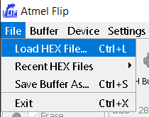
Just use FLIP Software from ATMEL: https://www.microchip.com/en-us/development-tool/flip
Go to File -> Load HEX File select at90blink.hex or leoblink.hex
Click in Select Target Device Icon
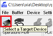
Select AT90USB1287 or ATMEGA32U4
Click in Select a Communication Medium Icon
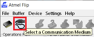
Select USB and click Open
Select: Erase, Blank Check, Program, Verify
Click Run
Click Start Application (select Reset)
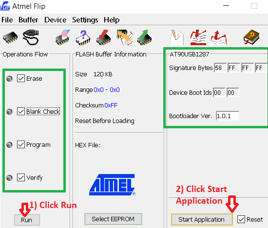
If some fails repeat the entire process.
at90 / leo - bootloaderhid
HID bootloader, allowing for device FLASH programming through the supplied command line software, which is a modified version of Paul’s TeensyHID Command Line loader code from PJRC.
Use HID bootloader in ATMEGA32U4:
- press LEO reset + LEO boot button at same time
- stop pressing reset button
- wait a little and stop pressing LEO boot button
Use HID bootloader in AT90USB1287:
- you must flash leousbswitchtoat90.hex to ATMEGA32U4
- reconnect rpk2 board
- press AT90 reset + AT90 boot button at same time
- stop pressing reset button
- wait a little and stop pressing AT90 boot button
Check if the bootloader is detected by Windows:
wmic path CIM_LogicalDevice where "DeviceID like '%6969%' and DeviceID like '%HID%'" get /value
Use the python tool to flash at90blink.hex in AT90USB1287:
python hid_bootloader_cli_python.py at90usb1287 at90blink.hex
Use the python tool to flash leoblink.hex in ATMEGA32U4:
python hid_bootloader_cli_python.py atmega32u4 leoblink.hex
Use hid_bootloader_cli_win_vs.exe to flash at90blink.hex in AT90USB1287:
hid_bootloader_cli_win_vs.exe -v -w -mmcu=at90usb1287 at90blink.hex
Use hid_bootloader_cli_win_vs.exe to flash leoblink.hex in ATMEGA32U4:
hid_bootloader_cli_win_vs.exe -v -w -mmcu=atmega32u4 leoblink.hex
For Linux you can use hid_bootloader_cli_unix (the same syntax hid_bootloader_cli_win_vs.exe)
at90 / leo - bootloadermsc
Mass Storage device bootloader, capable of reading and writing a new binary firmware image file, to load firmware onto the AVR.
Use mass storage bootloader in ATMEGA32U4:
- press LEO reset + LEO boot button at same time
- stop pressing reset button
- wait a little and stop pressing LEO boot button
Use mass storage in AT90USB1287:
- you must flash leousbswitchtoat90.hex to ATMEGA32U4
- reconnect rpk2 board
- press AT90 reset + AT90 boot button at same time
- stop pressing reset button
- wait a little and stop pressing AT90 boot button
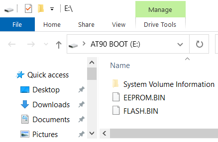
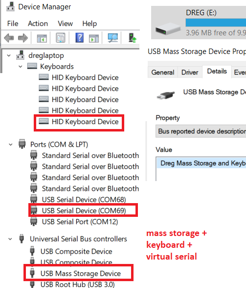
Now it appears like a new pendrive connected to the machine:
This bootloader is compatible with all operating systems that support the FAT12 file system format.
To reprogram the device, overwrite a file stored on the virtual FAT filesystem with a new binary (BIN format) image.
Remember to safely remove your device from the host using the host OS’s ejection APIs, to ensure all data is correctly flushed to the bootloader’s virtual filesystem and not cached in the OS’s file system driver.
The current device firmware can be read from the device by reading a file from the virtual FAT filesystem. Two files will be present:
- FLASH.BIN representing the AVR’s internal flash memory
- EEPROM.BIN representing the AVR’s internal EEPROM memory
To convert an existing Intel HEX (.HEX) program file to a binary (.BIN) file suitable for this bootloader, run:
avr-objcopy -O binary -R .eeprom -R .fuse -R .lock -R .signature input.hex output.bin
AVR EEPROM data files in Intel HEX format (.EEP) uses a similar technique:
avr-objcopy -O binary input.eep output.bin
Example flashing leoblink.hex to ATMEGA32U4:
"C:\arduino\hardware\tools\avr\bin\avr-objcopy.exe" -I ihex leoblink.hex -O binary FLASH.BIN
Copy FLASH.BIN to Mass Storage (replacing the old file)
Eject device (like a pendrive)
Reconnect the board
leobootloaderarduino
This convert ATMEGA32U4 chip to a default Arduino Leonardo. Its a Caterina2 bootloader using LUFA (thx to https://github.com/facchinm/Arduino_avrusb_firmware).
This bootloader spoofs Arduino Leonardo VID and PID values, so the board is detected as Arduino Leonardo.
You can use the Arduino IDE and all libs without problems, also you can upload programs via normal Upload button in Arduino IDE.
replace flash and bootloaders via JTAG and ICSP
To replace a bootloader you need use a ICSP or a JTAG programmer.
These steps are also valid to flash the device without a bootloader.
WARNING: When you burn a flash using JTAG or ICSP the bootloader is removed and only the .hex programmed runs in the chip.
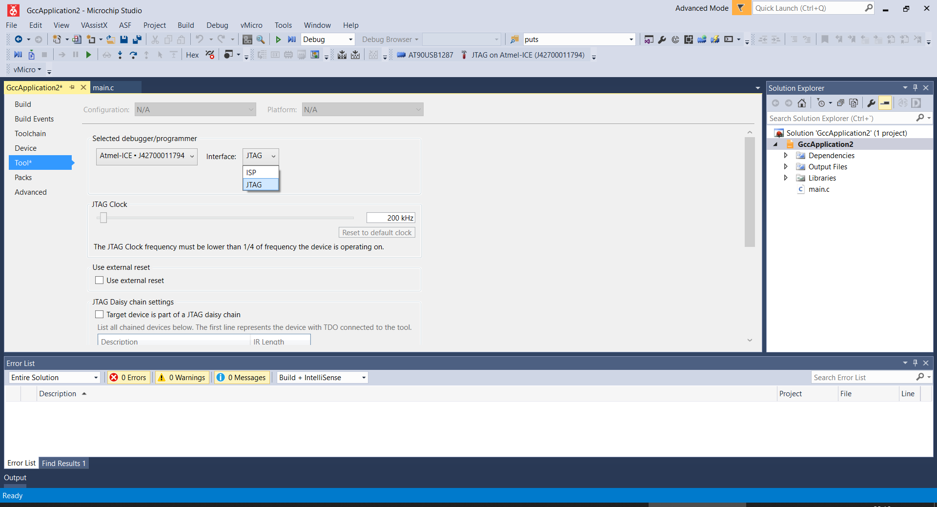
replace bootloader or flash in Microchip Atmel Studio using ATMEL ICE via JTAG
Connect JTAG (in correct position) to chip AVR-JTAG-Connector:
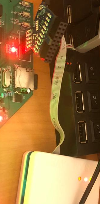
Connect the board to PC
Connect ATMEL ICE to PC
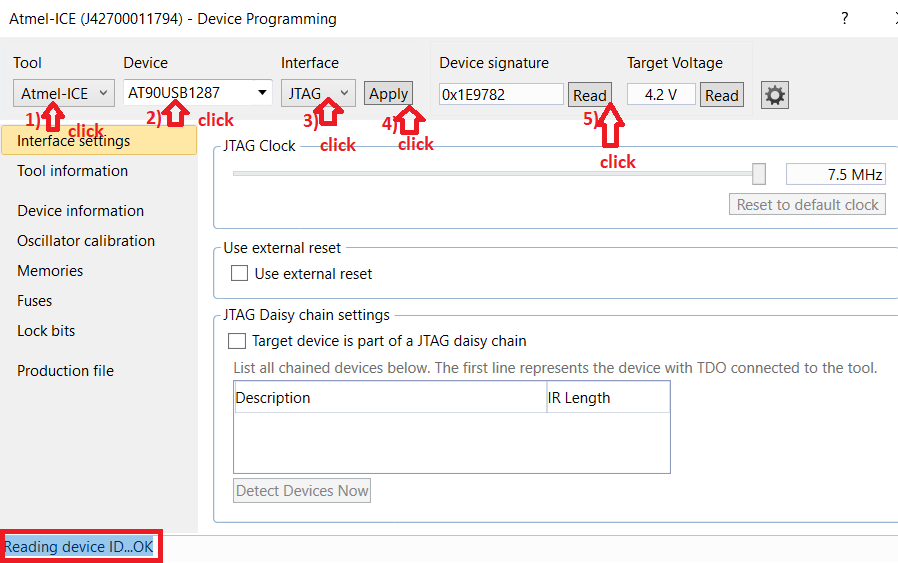
Open Microchip Atmel Studio
Go to Tools -> Device Programming
Select in Tool: Atmel ICE
Select in Device: AT90USB1287 or ATMEGA32U4
Select in Interface: JTAG
Click Apply
Click Read in Device Signature
Now you should read: Reading device ID…OK
Go to Memories
Select Erase device before programming
Select Verify Flash after programming
Select a bootloader .hex file to flash and click Program (the same for the EEPROM)
Now you should read:
Erasing device… OK Programming Flash…OK Verifying Flash…OK
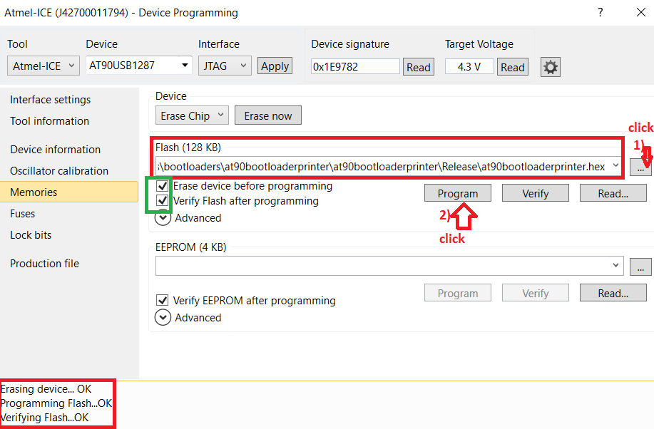
And done, your new bootloader is burned, you can close Microchip Atmel Studio.
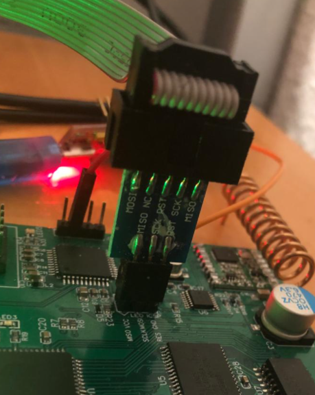
replace bootloader or flash via ICSP USBasp-clone using avrdude
Connect your USBasp-clone (in correct position) to ICSP chip (AT90USB1287 or ATMEGA32U4)
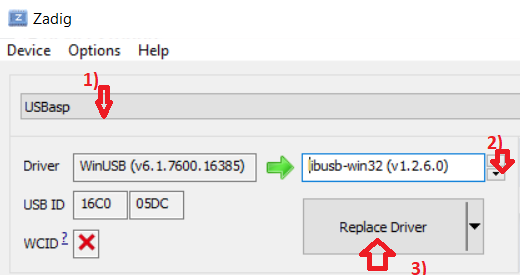
Install Zadig Software, Zadig is a Windows application that installs generic USB drivers, such as WinUSB, libusb-win32/libusb0.sys or libusbK, to help you access USB devices:
Open Zadig
Go To Options -> List All Devices
Select USBasp
Click in rows and select libusb-win32 driver
Click Replace Driver
run a cmd.exe as Administrator and execute avrdude, example flashing leoblink.hex to ATMEGA32U4:
"C:\arduino\hardware\tools\avr\bin\avrdude.exe" -v -v -v -C "C:\arduino\hardware\tools\avr\etc\avrdude.conf" -c usbasp-clone -p atmega32u4 -P USB -U flash:w:"leoblink.hex":i -v -v
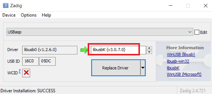
if avrdude fails try again all steps but using libusbK in Zadig:
How to program ATMEGA32U4 and AT90USB1287 using Microchip Atmel Studio + USBasp-clone
Open Microchip Atmel Studio
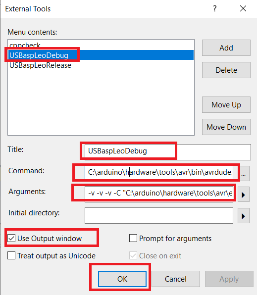
USBaspLeoDebug
Go Tools –> External Tools
Click Add
Title: USBaspLeoDebug
Command: C:\arduino\hardware\tools\avr\bin\avrdude.exe
Arguments: -v -v -v -C “C:\arduino\hardware\tools\avr\etc\avrdude.conf” -c usbasp-clone -p atmega32u4 -P USB -U flash:w:”$(ProjectDir)\Debug$(TargetName).hex”:i -v -v
Select: Use Output Window
Click OK
USBaspLeoRelease
Go Tools –> External Tools
Click Add
Title: USBaspLeoRelease
Command: C:\arduino\hardware\tools\avr\bin\avrdude.exe
Arguments: -v -v -v -C “C:\arduino\hardware\tools\avr\etc\avrdude.conf” -c usbasp-clone -p atmega32u4 -P USB -U flash:w:”$(ProjectDir)\Release$(TargetName).hex”:i -v -v
Select: Use Output Window
Click OK
USBaspAT90Debug
Go Tools –> External Tools
Click Add
Title: USBaspAT90Debug
Command: C:\arduino\hardware\tools\avr\bin\avrdude.exe
Arguments: -v -v -v -C “C:\arduino\hardware\tools\avr\etc\avrdude.conf” -c usbasp-clone -p at90usb1287 -P USB -U flash:w:”$(ProjectDir)\Debug$(TargetName).hex”:i -v -v
Select: Use Output Window
Click OK
USBaspAT90Release
Go Tools –> External Tools
Click Add
Title: USBaspAT90Release
Command: C:\arduino\hardware\tools\avr\bin\avrdude.exe
Arguments: -v -v -v -C “C:\arduino\hardware\tools\avr\etc\avrdude.conf” -c usbasp-clone -p at90usb1287 -P USB -U flash:w:”$(ProjectDir)\Release$(TargetName).hex”:i -v -v
Select: Use Output Window
Click OK
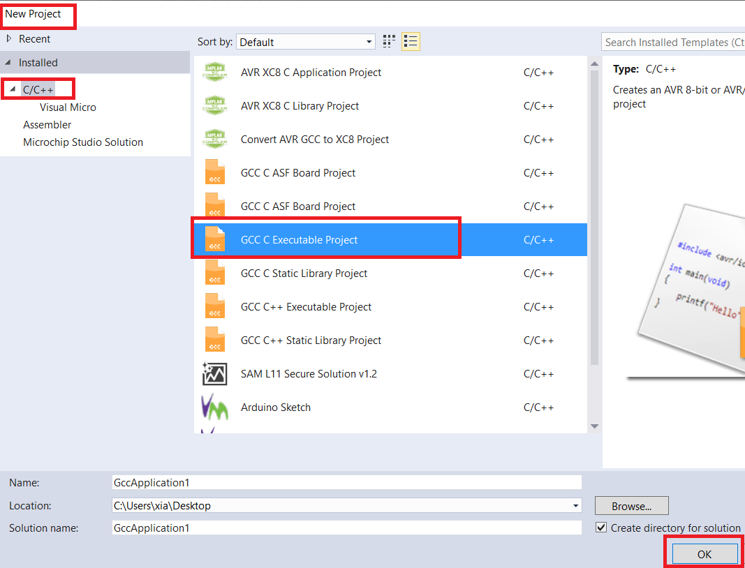
creating a project for ATMEGA32U4
Go to File –> New –> Project
C/C++ –> GCC C Executable
Click Ok
In Device Family: All
Search and select ATMEGA32U4
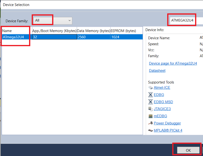
Click Ok
Done!
Paste this code in main.c
#define F_CPU 16000000UL

#include <avr/io.h>
#include <util/delay.h>
#include <avr/wdt.h>
#define clear_bit(sfr, bit) (_SFR_BYTE(sfr) &= ~_BV(bit))
#define set_bit(sfr, bit) (_SFR_BYTE(sfr) |= _BV(bit))
#define toogle_bit(sfr, bit) (_SFR_BYTE(sfr) ^= _BV(bit))

int main(int argc, char **argv)
{
    MCUSR &= ~_BV(WDRF);
    wdt_disable();

    set_bit(DDRB, DDB5);
    clear_bit(PORTB, PB5);
    set_bit(DDRB, DDB4);
    clear_bit(PORTB, PB4);

    while (1)
    {
        set_bit(PORTB, PB4);
        _delay_ms(1000);
        set_bit(PORTB, PB5);
        _delay_ms(1000);
        clear_bit(PORTB, PB4);
        clear_bit(PORTB, PB5);
        _delay_ms(200);
        set_bit(PORTB, PB5);
        _delay_ms(1000);
        clear_bit(PORTB, PB4);
        clear_bit(PORTB, PB5);
        _delay_ms(1000);
    }

    return 0;
}
Now Compile the project in Debug Mode (Solution Configuration):
Select Debug:
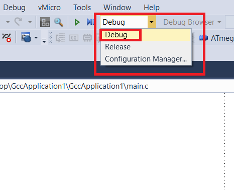
Go to Build –> Rebuild Solution
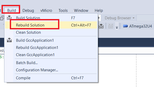
Now you can see in Output Window:
....
Build succeeded.
========== Rebuild All: 1 succeeded, 0 failed, 0 skipped ==========
Now you have the .hex and .elf output files in the project folder:
project_name\project_name\Debug\project_name.hex
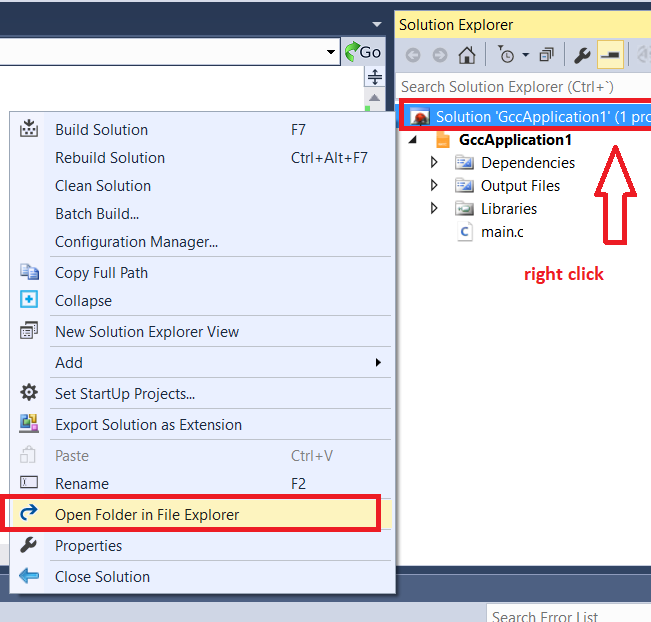
To Open the project Directory right click in Solution –> Open Folder in File Explorer
You can flash it via bootloader, JTAG, ICSP ..
Now, connect USBasp in correct order to rpk2.
Connect rpk2 to PC.
Connect USBasp to PC.
Go to Tools –> USBaspLeoDebug
Also you can compile in Release mode and for flash it just use Tools –> USBaspLeoRelease
Example of correct avrdude output (USBaspLeoRelease): 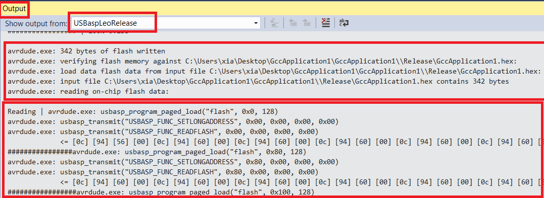
creating a project for AT90USB1287
Go to File –> New –> Project
C/C++ –> GCC C Executable
Click Ok
In Device Family: All
Search and select AT90USB1287
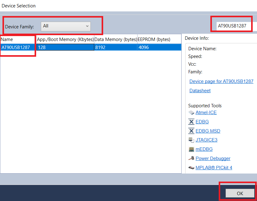
Click Ok
Done!
Paste this code in main.c
#define F_CPU 16000000UL

#include <avr/io.h>
#include <util/delay.h>
#include <avr/wdt.h>
#include <avr/sfr_defs.h>
#define clear_bit(sfr, bit) (_SFR_BYTE(sfr) &= ~_BV(bit))
#define set_bit(sfr, bit) (_SFR_BYTE(sfr) |= _BV(bit))
#define toogle_bit(sfr, bit) (_SFR_BYTE(sfr) ^= _BV(bit))

int main(int argc, char **argv)
{
    MCUSR &= ~_BV(WDRF);
    wdt_disable();

    CLKPR = (1<<CLKPCE);
    CLKPR = 0;

    set_bit(DDRD, DDD6);
    clear_bit(PORTD, PD6);
    set_bit(DDRD, DDD7);
    clear_bit(PORTD, PD7);

    while (1)
    {
        set_bit(PORTD, PD6);
        _delay_ms(1000);
        set_bit(PORTD, PD7);
        _delay_ms(1000);
        clear_bit(PORTD, PD6);
        clear_bit(PORTD, PD7);
        _delay_ms(200);
        set_bit(PORTD, PD7);
        _delay_ms(1000);
        clear_bit(PORTD, PD6);
        clear_bit(PORTD, PD7);
        _delay_ms(1000);
    }

    return 0;
}
Now Compile the project in Debug Mode (Solution Configuration):
Select Debug:
Go to Build –> Rebuild Solution
Now you can see in Output Window:
....
Build succeeded.
========== Rebuild All: 1 succeeded, 0 failed, 0 skipped ==========
Now you have the .hex and .elf output files in the project folder:
project_name\project_name\Debug\project_name.hex
To Open the project Directory right click in Solution –> Open Folder in File Explorer
You can flash it via bootloader, JTAG, ICSP ..
Now, connect USBasp in correct order to rpk2.
Connect rpk2 to PC.
Connect USBasp to PC.
Go to Tools –> USBaspAT90Debug
Also you can compile in Release mode and for flash it just use Tools –> USBaspAT90Release
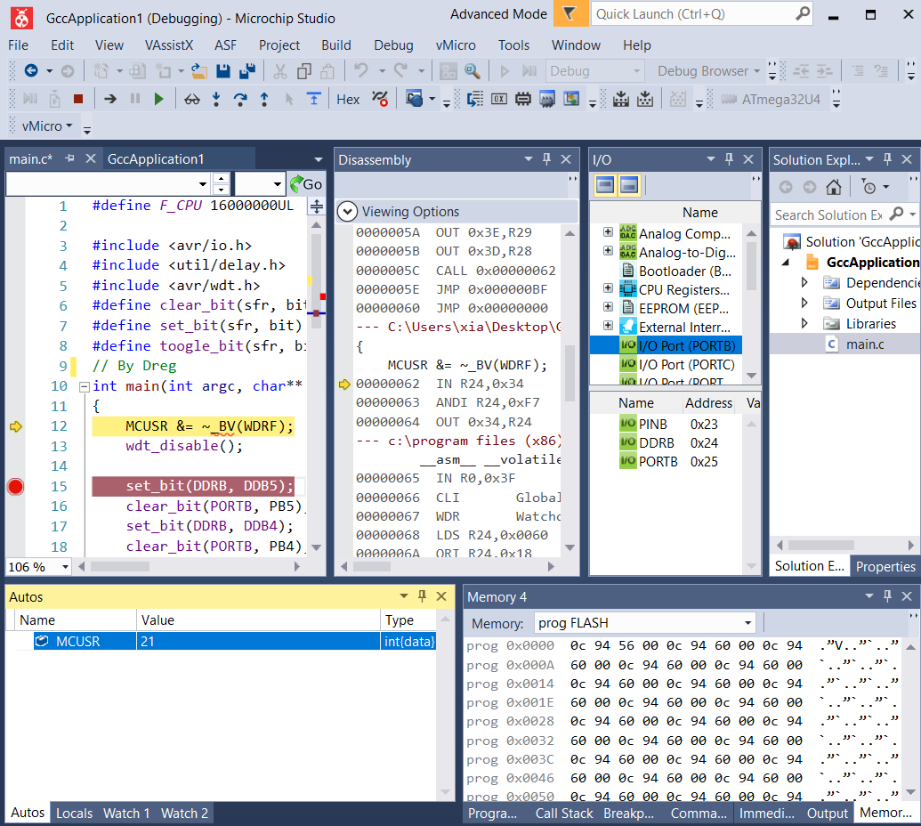
How to program and debug ATMEGA32U4 and AT90USB1287 via JTAG using Microchip Atmel Studio + ATMEL ICE
Open the solution project (.atsln)
Select Debug to compile
Go to Debug -> Start Debugging and break
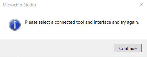
Press Continue in the message box
Selected debugger / programmer: Atmel-ICE
Interface: JTAG (if you want use ICSP connector only for programming select ISP)
Go to File -> Save All
Go to Debug -> Start Debugging and break
and done, You can debug your project, put breakpoints etc.
To flash a Release version or Debug version without Debugging just go to Debug -> Start Without Debugging
For flash also you can use ATMEL-ICE ICSP connector
How to program ATMEGA32U4 using Arduino IDE + printer bootloader
Open Arduino IDE
Go to File –> New
Paste this code:
#define LED1 8
#define LED2 9

void initVariant(void)
{
  //modified by Dreg
  asm volatile ("sbi 0x10,0");
  asm volatile ("cbi 0x11,0");
  asm volatile ("sbi 0x10,1");
  asm volatile ("sbi 0x11,1");
  // -
}

void setup()
{
  pinMode(LED1, OUTPUT);
  pinMode(LED2, OUTPUT);

  delay(1000);
}

void loop()
{
  digitalWrite(LED1, HIGH);
  delay(500);
  digitalWrite(LED2, HIGH);
  delay(500);
  digitalWrite(LED1, LOW);
  delay(500);
  digitalWrite(LED2, LOW);
  delay(500);
}
Go to File -> Save
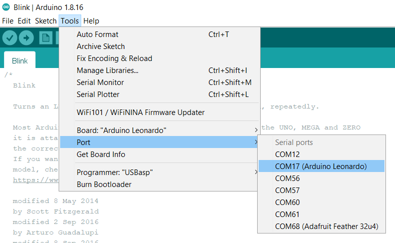
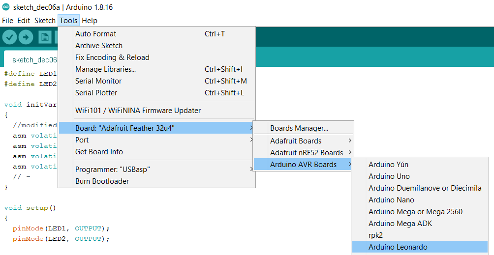
Now, Go Tools -> Board –> Arduino AVR Boards —> Arduino Leonardo
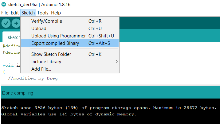
Go to Sketch –> Export Compiled Binary
Open Sketch folder
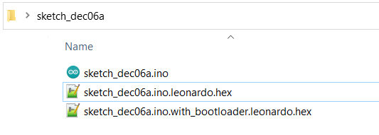
Open sketch_name.ino.leonardo with Notepad
Enable bootloader mode in ATMEGA32U4
Print it!
Done!
How to port the previous Arduino Sketch project to Microchip Atmel Studio (better IDE with JTAG Debugging)
Open Microchip Atmel Studio
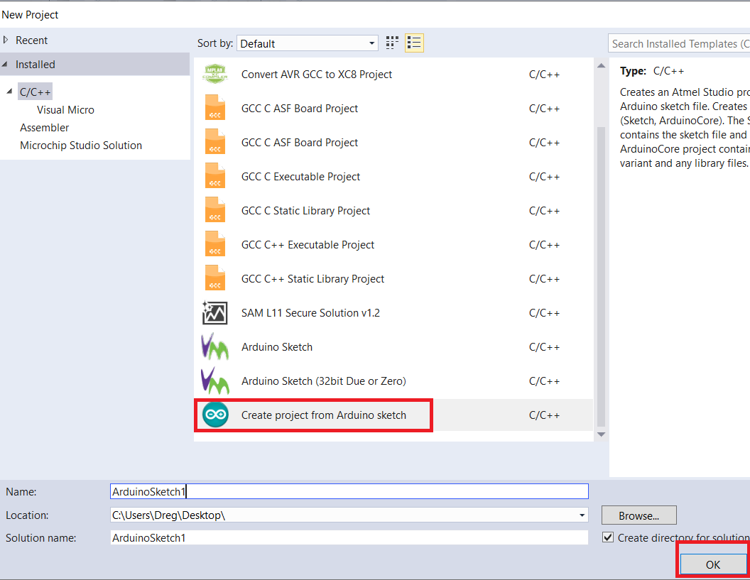
Go to File —> New —> Project
Select Create Project From Arduino Sketch
Click Ok
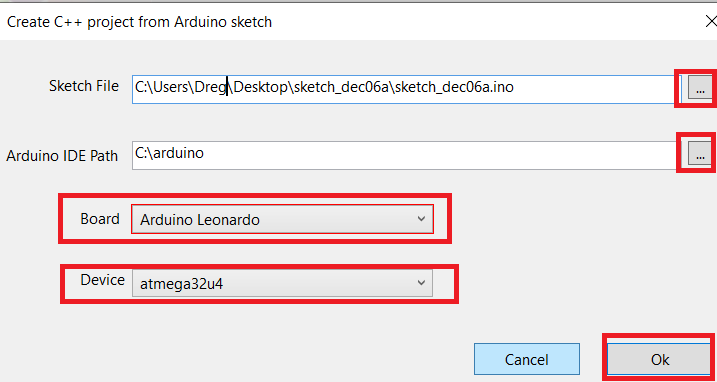
Select Sketch File
Select your Arduino Installation Path
Board: Arduino Leonardo
Device: atmega32u4
Click Ok
Done!
Now you can build the project
Go to Build –> Rebuild Solution
Now you have the .hex file in:
sketch_name\sketch_name\sketch_name\Debug\sketch_name.hex
or:
sketch_name\sketch_name\sketch_name\Release\sketch_name.hex
You can print it in bootloader mode or flash it directly from Microchip Atmel Studio using JTAG (or ICSP via Atmel ICE)
Now you can debug this project like a normal project.
How to program AT90USB1287 using Arduino IDE + teensyduino + printer bootloader
Open Arduino IDE with teensyduino previously installed: https://www.pjrc.com/teensy/td_download.html
Go to File –> New
Paste this code:
#define LED1 6
#define LED2 7

#include <avr/io.h>
#include <avr/wdt.h>

int InitAT90(void)
{
    MCUSR &= ~(1<<WDRF);
    wdt_disable();
    CLKPR = (1<<CLKPCE);
    CLKPR = 0;
    return 1;
}

void initVariant(void)
{
  InitAT90();
  delay(3000);
}

void setup()
{
  InitAT90();
  pinMode(LED1, OUTPUT);
  pinMode(LED2, OUTPUT);
}

void loop()
{
  digitalWrite(LED1, HIGH);
  delay(500);
  digitalWrite(LED2, HIGH);
  delay(500);
  digitalWrite(LED2, LOW);
  delay(500);
  digitalWrite(LED1, LOW);
  delay(500);
}
Go to File -> Save
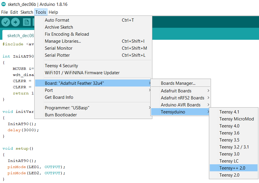
Now, Go Tools -> Board –> Teensyduino —> Tennsy++ 2.0
Go to Sketch –> Export Compiled Binary
Open Sketch folder
Open sketch_name.ino.TEENSY2PP.hex with Notepad
Enable bootloader mode in AT90USB1287
Print it!
Done, you can use Tennsy++ 2.0 libs in Arduino! https://www.pjrc.com/teensy/td_libs.html
How to port the previous Teensy Arduino Sketch project to Microchip Atmel Studio (better IDE with JTAG Debugging)
You need install Visual Micro in Microchip Atmel Studio: https://www.visualmicro.com/
Open Microchip Atmel Studio
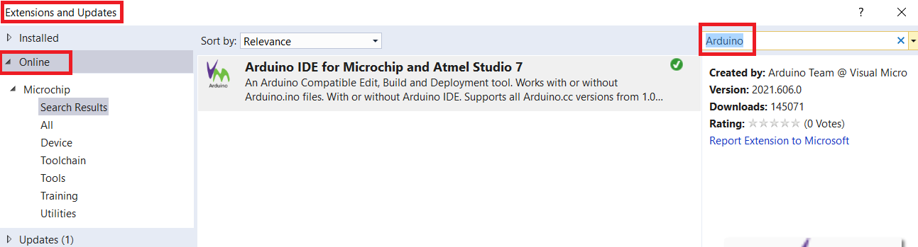
Go to Tools -> Extensions and Updated
Go to online
Search Arduino
Download and Install Visual Micro:
restart Microchip Atmel Studio
Go to File –> Open —> Arduino Project
Search the Teensy Arduino Sketch project
Go to Build –> Rebuild Solution
And now you have the .hex ready to flash in: sketch_name\Release\sketch_name.hex or: sketch_name\Debug\sketch_name.hex
Open sketch_name.ino.hex with Notepad
Enable bootloader mode in AT90USB1287
Print it!
Now save the Microchip Atmel Studio Project, Go to File –> Save all
How to JTAG debug the teensy project
You need create other project only for debugging
Go to File –> Open —> Open Object File For Debugging
Select the Object File To Debug: Search sketch_name\Debug\sketch_name.elf
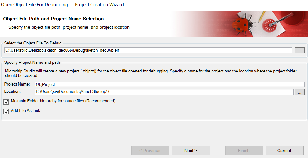
Click Next
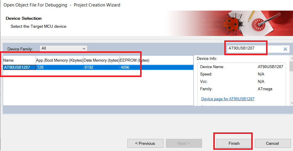
Select device AT90USB1287
Click Finish
Click Finish again
Go to Debug –> Start Debugging and Brak
And done you can use this project only for debugging via JTAG
demo firmware
All LUFA + own demos adapted for rpk2 (some demos are not 100% adapted yet, but it works)
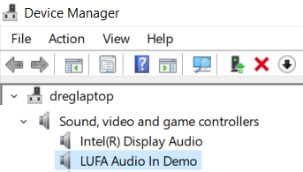
at90audioinput
Audio demonstration application.
This gives a simple reference application for implementing a USB Audio Input device using the basic USB Audio 1.0 drivers in all modern OSes (i.e. no special drivers required).
On start-up the system will automatically enumerate and function as a USB microphone.
By default, the demo will produce a square wave test tone when the board button is pressed.
If USE_TEST_TONE is not defined in the project makefile, incoming audio from the ADC channel 1 will be sampled and sent to the host computer instead.
When in microphone mode, connect a microphone to the ADC channel 2.
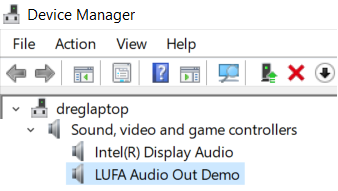
at90audiooutput
Audio demonstration application.
This gives a simple reference application for implementing a USB Audio Output device using the basic USB Audio 1.0 drivers in all modern OSes (i.e. no special drivers required).
On start-up the system will automatically enumerate and function as a USB speaker.
Outgoing audio will output in 8-bit PWM onto the timer 3 output compare channel A for AUDIO_OUT_MONO mode, on timer 3 channels A and B for AUDIO_OUT_STEREO and on PORTC as a signed mono sample for AUDIO_OUT_PORTC.
Audio output will also be indicated on the board LEDs in all modes. Decouple audio outputs with a capacitor and attach to a speaker to hear the audio.
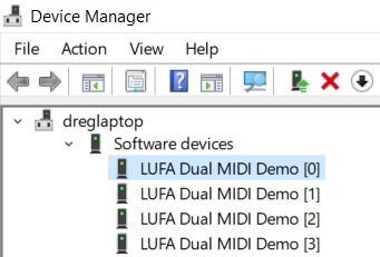
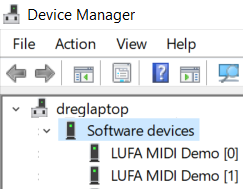
at90dualmidi
Dual MIDI demonstration application. This gives a simple reference application for implementing the USB-MIDI class in USB devices.
It is built upon the USB Audio class.
Joystick movements are translated into note on/off messages and are sent to the host PC as MIDI streams which can be read by any MIDI program supporting MIDI IN devices.
If the HWB is not pressed, the first virtual MIDI cable to the host is used.
If the HWB is pressed, then the second virtual cable is selected.
This device implements MIDI-THRU mode, with the IN MIDI data being generated by the device itself.
OUT MIDI data is discarded.
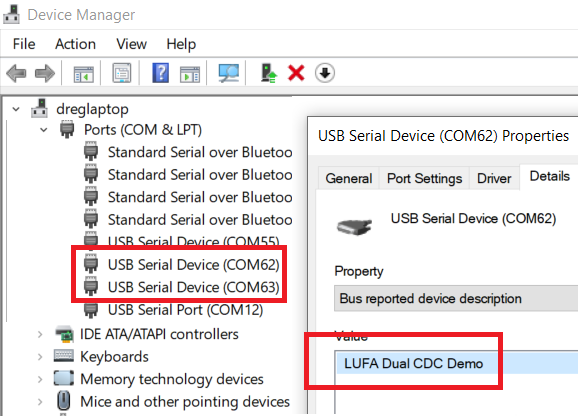
at90dualvirtualserial
Dual Communications Device Class demonstration application.
This gives a simple reference application for implementing a composite device with dual CDC functions acting as a pair of virtual serial ports.
This demo uses Interface Association Descriptors to link together the pair of related CDC descriptors for each virtual serial port, which may not be supported in all OSes - Windows Vista is supported, as is XP (although the latter may need a hotfix to function).
Joystick actions are transmitted to the host as strings through the first serial port.
The device does not respond to serial data sent from the host in the first serial port.
The second serial port echoes back data sent from the host.
After running this demo for the first time on a new computer, may you will need to supply the .INF file located in this demo project’s directory as the device’s driver when running under Windows.
This will enable Windows to use its inbuilt CDC drivers, negating the need for custom drivers for the device.
Other Operating Systems should automatically use their own inbuilt CDC-ACM drivers.
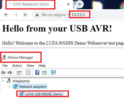
at90ethernet
Remote Network Driver Interface demonstration application.
This gives a simple reference application for implementing a CDC RNDIS device acting as a simple network interface for ethernet packet exchange.
RNDIS is a proprietary Microsoft standard;
this demo will only work on Windows 2000 (manually patched with the Microsoft RNDIS hotfix) and above (with no manual patches), or on the latest Linux kernels.
Before running, you will need to install the INF file that is located in the project directory.
This will enable Windows to use its inbuilt RNDIS drivers, negating the need for special Windows drivers for the device.
To install, right-click the .INF file and choose the Install option.
If Windows 2000 is used, the Microsoft INF file in the hotfix will need to be altered to use the VID/PID of the demo and then chosen instead of the LUFA RNDIS INF file when prompted.
When enumerated, this demo will install as a new network adapter which ethernet packets can be sent to and received from.
Running on top of the adapter is a very simple TCP/IP stack with a HTTP webserver and TELNET host which can be accessed through a web browser at IP address 10.0.0.2:80 or through a TELNET client at 10.0.0.2:25.
This device also supports ping echos via the ICMP protocol.
The TCP/IP stack in this demo has a number of limitations and should serve as an example only - it is not fully featured nor compliant to the TCP/IP specification.
For complete projects, it is recommended that it be replaced with an external open source TCP/IP stack that is feature complete, such as the uIP stack.
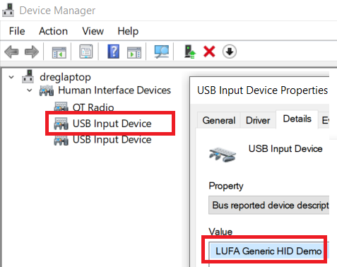
at90generichid
Generic HID device demonstration application.
This gives a simple reference application for implementing a generic HID device, using the basic USB HID drivers in all modern OSes (i.e. no special drivers required).
By default it accepts and sends up to 8 byte reports to and from a USB Host, and transmits the last sent report back to the host.
On start-up the system will automatically enumerate and function as a vendor HID device.
When controlled by a custom HID class application, reports can be sent and received by both the standard data endpoint and control request methods defined in the HID specification.ers required).
By default it accepts and sends up to 8 byte reports to and from a USB Host, and transmits the last sent report back to the host.
On start-up the system will automatically enumerate and function as a vendor HID device.
When controlled by a custom HID class application, reports can be sent and received by both the standard data endpoint and control request methods defined in the HID specification.
Just connect the board and execute one of the programs:
- test_generic_hid_libusb.js
- test_generic_hid_winusb.py
- test_generic_hid_libusb.py
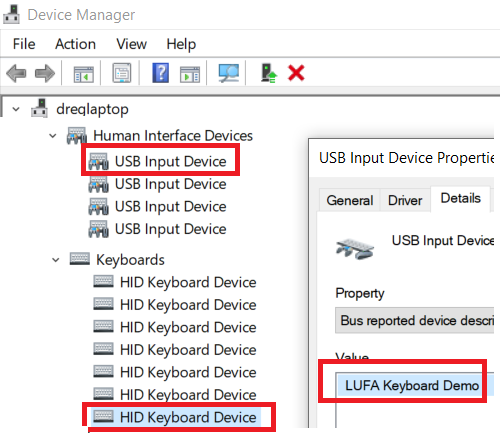
at90keyboard
Keyboard demonstration application. This gives a simple reference application for implementing a USB Keyboard using the basic USB HID drivers in all modern OSes (i.e. no special drivers required).
It is boot protocol compatible, and thus works under compatible BIOS as if it was a native keyboard (e.g. PS/2).
On start-up the system will automatically enumerate and function as a keyboard when the USB connection to a host is present.
To use the keyboard example, manipulate the joystick to send the letters a, b, c, d and e.
See the USB HID documentation for more information on sending keyboard event and key presses.
Unlike other LUFA Keyboard demos, this example shows explicitly how to send multiple key presses inside the same report to the host.
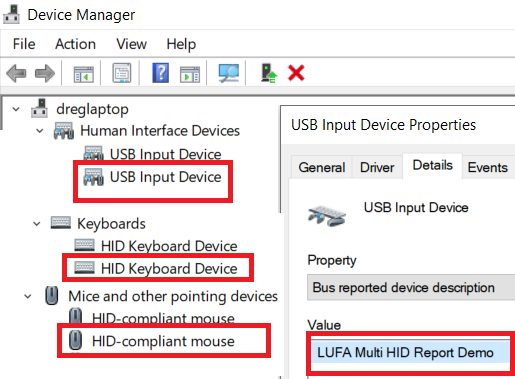
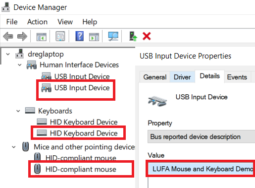
at90keyboardmouse
Keyboard/Mouse demonstration application, using a single HID interface.
This gives a simple reference application for implementing a multiple HID report device containing both USB Keyboard and USB Mouse functionality using the basic USB HID drivers in all modern OSes (i.e. no special drivers required).
This example uses a single HID interface that is shared between the two functions.
On start-up the system will automatically enumerate and function as a keyboard when the USB connection to a host is present and the HWB is not pressed.
When enabled, manipulate the joystick to send the letters a, b, c, d and e.
See the USB HID documentation for more information on sending keyboard event and key presses.
When the HWB is pressed, the mouse mode is enabled.
When enabled, move the joystick to move the pointer, and push the joystick inwards to simulate a left-button click.
at90keyboardmousenomulti
Keyboard/Mouse demonstration application.
This gives a simple reference application for implementing a composite device containing both USB Keyboard and USB Mouse functionality using the basic USB HID drivers in all modern OSes (i.e. no special drivers required).
This example uses two separate HID interfaces for each function.
It is boot protocol compatible, and thus works under compatible BIOS as if it was a native keyboard and mouse (e.g. PS/2).
On start-up the system will automatically enumerate and function as a keyboard when the USB connection to a host is present and the HWB is not pressed.
When enabled, manipulate the joystick to send the letters a, b, c, d and e.
See the USB HID documentation for more information on sending keyboard event and key presses.
When the HWB is pressed, the mouse mode is enabled. When enabled, move the joystick to move the pointer, and push the joystick inwards to simulate a left-button click.
at90midi
MIDI demonstration application.
This gives a simple reference application for implementing the USB-MIDI class in USB devices.
It is built upon the USB Audio class.
Joystick movements are translated into note on/off messages and are sent to the host PC as MIDI streams which can be read by any MIDI program supporting MIDI IN devices.
If the HWB is not pressed, channel 1 (default piano) is used.
If the HWB is pressed, then channel 10 (default percussion) is selected.
This device implements MIDI-THRU mode, with the IN MIDI data being generated by the device itself. OUT MIDI data is discarded.
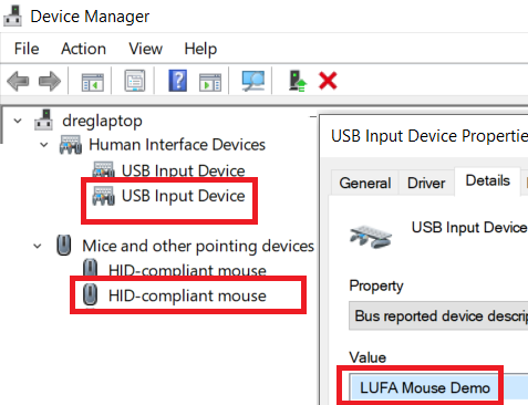
at90mouse
Mouse demonstration application.
This gives a simple reference application for implementing a USB Mouse using the basic USB HID drivers in all modern OSes (i.e. no special drivers required).
It is boot protocol compatible, and thus works under compatible BIOS as if it was a native mouse (e.g. PS/2).
On start-up the system will automatically enumerate and function as a mouse when the USB connection to a host is present.
To use the mouse, move the joystick to move the pointer, and push the joystick inwards to simulate a left-button click.
The HWB serves as the right mouse button.
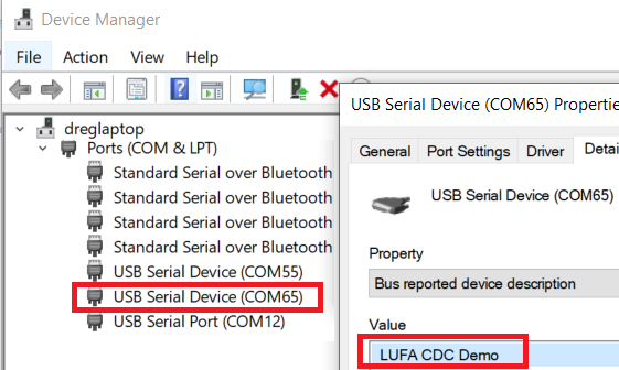
at90virtualserial
Communications Device Class demonstration application.
This gives a simple reference application for implementing a CDC device acting as a virtual serial port.
Joystick actions are transmitted to the host as strings.
The device does not respond to serial data sent from the host.
After running this demo for the first time on a new computer, may you will need to supply the .INF file located in this demo project’s directory as the device’s driver when running under Windows.
This will enable Windows to use its inbuilt CDC drivers, negating the need for custom drivers for the device.
Other Operating Systems should automatically use their own inbuilt CDC-ACM drivers.
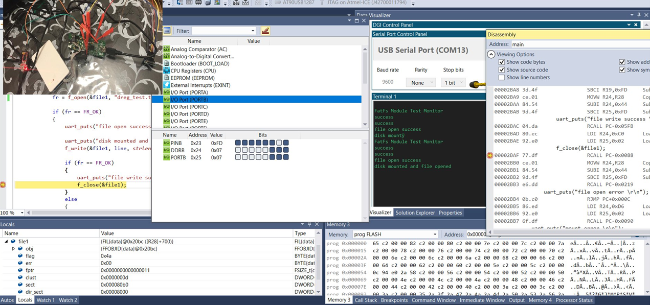
at90masskeyboardfatfs - at90masskeyboard2gbsd - at90masskeyboardvirtualserialfatfs - at90masskeyboardvirtualserial2gbsd
Combined Mass Storage and Keyboard demonstration application.
This gives a simple reference application for implementing a dual class USB Mass Storage and USB HID Keyboard device using the basic USB UFI and HID drivers in all modern OSes (i.e. no special drivers required).
On start-up the system will automatically enumerate and function as an external mass storage device (which may be formatted and used in the same manner as commercial USB Mass Storage devices) and a USB keyboard.
You will need to format the mass storage drive upon first run of this demonstration - as the device acts only as a data block transport between the host and the storage media, it does not matter what file system is used, as the data interpretation is performed by the host and not the USB device.
Keys on the USB keyboard can be pressed by moving the board’s Joystick.
The USB control endpoint is managed entirely by the library using endpoint interrupts, as the INTERRUPT_CONTROL_ENDPOINT option is enabled.
This allows for the host to reset the Mass Storage device state during long transfers without the need for complicated polling logic.
demos with virtualserial string inside adds a CDC device acting as a virtual serial port:
- mass storage +
- keyboard +
- virtual serial port
demos with 2gbsd string inside only works with 2 GB SD CARDS (not SDHC)
at90extmem
Example using and testing external memory 512Kb RAM AS7C4096A-12TCN
at90readwritespisd
Example using a 2 GB SD CARDS (not SDHC) via SPI
at90serialhello
Example hello world via chip UART. Pins accesible in rpk2 board
at90softuartx
Example using software UART only for transmit (using PB5)
at90swuart
Software UART for AVR like AltSoftSerial or NeoICSerial without Arduino layer
This library is like AltSoftSerial:
- Can simultaneously transmit and receive. Minimal interference with simultaneous use of HardwareSerial and other libraries
- Consumes a 16 bit timer (and will not work with any libraries which need that timer) and disables some PWM pins
- Its possible to switch between TIMER1 and TIMER3 with a simple #define
- Can be sensitive to interrupt usage by other libraries
- Capable of running up to 31250 baud on 16 MHz AVR. Slower baud rates are recommended when other code may delay library’s interrupt response
- More info about Interrupt Latency Requirements, Timer Usage, Usable Speed: https://www.pjrc.com/teensy/td_libs_AltSoftSerial.html
https://github.com/therealdreg/at90swuart
at90timers
Example using TIMER1 and TIMER3 (both 16 timers) generating a 100 Hz delay. (needed by FatFs).
at90buttons
Example using buttons and leds in the rpk2 board.
at90blink
Blink leds in the rpk2 board.
at90sketchbasicexample
Example programming AT90USB1287 board with Arduino + Teensyduino
In Arduino IDE:
Go to Tools –> Board –> Teensyduino –> Teensy++ 2.0
USB Type: Serial
CPU SPEED: 16mhz
leoaltsoftserial
Software UART AltSoftSerial
- Can simultaneously transmit and receive. Minimal interference with simultaneous use of HardwareSerial and other libraries
- Consumes a 16 bit timer (and will not work with any libraries which need that timer) and disables some PWM pins
- Its possible to switch between TIMER1 and TIMER3 with a simple #define
- Can be sensitive to interrupt usage by other libraries
- Capable of running up to 31250 baud on 16 MHz AVR. Slower baud rates are recommended when other code may delay library’s interrupt response
- More info about Interrupt Latency Requirements, Timer Usage, Usable Speed: https://www.pjrc.com/teensy/td_libs_AltSoftSerial.html
leoblink
Blink leds in the rpk2 board.
leobuttons
Example using buttons and leds in the rpk2 board.
leohellowkeyboard
Demo using ATMEGA32U4 like a Keyboard
leorfrecver
Demo using RFM69HCW 433MHz module as a reciver module
leosketchbasicexample
Example of Arduino Sketch for ATMEGA32U4
leousbswitchtoat90
Example of how to use USB SWITCH
leoencchat
AES encrypted RF chat between rpk2 board & feather 32u4
leowinbondflashdriver
A generic driver + sample of usage for W25Q512JV flash memory over SPI using ATmega32u4
By Jusepe @itasahobby winbond_flash_driver
adafruit_feather_32u4 demos
Demos for Adafruit Feather 32u4 using RFM69HCW 433MHz module as a sender or reciver module
adafruit_feather_32u4_rf_leoencchat
AES encrypted RF chat between rpk2 board & feather 32u4
evilmass
Evil Mass Storage is a proof of concept USB composite device which demonstrates an end-to-end solution that infiltrates an isolated-offline-network and covertly extracts data over both radio frequency or close access covert storage while hiding from forensic analysis.
- info: evil mass storage
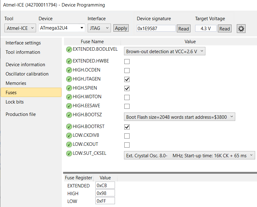
ATMEGA32U4 fuses
(factory: ex 0xF3, hi 0x99, lo 0x5E)
- extended: 0xcb
- high: 0x98
- low: 0xff
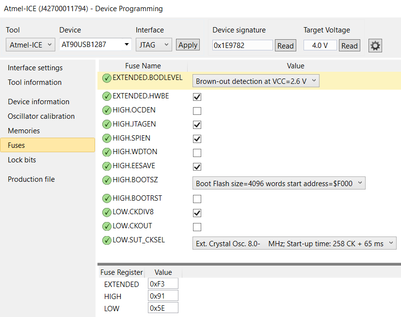
AT90USB1297 fuses
(factory: ex 0xF3, hi 0x99, lo 0x5E)
- extended: 0xf3
- high: 0x91
- low: 0x5e
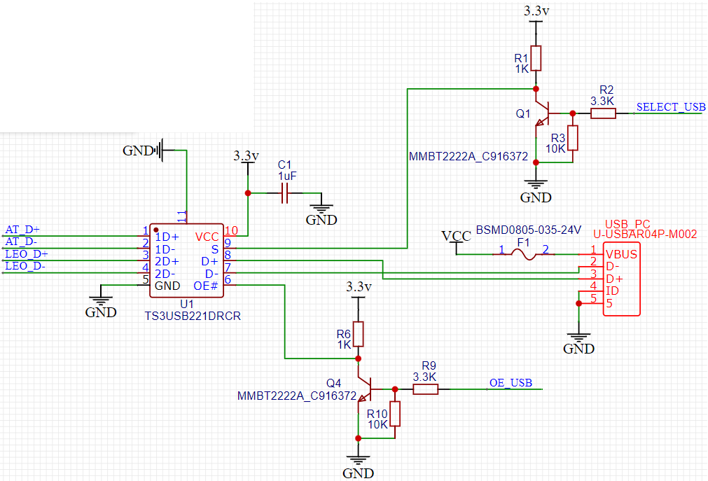
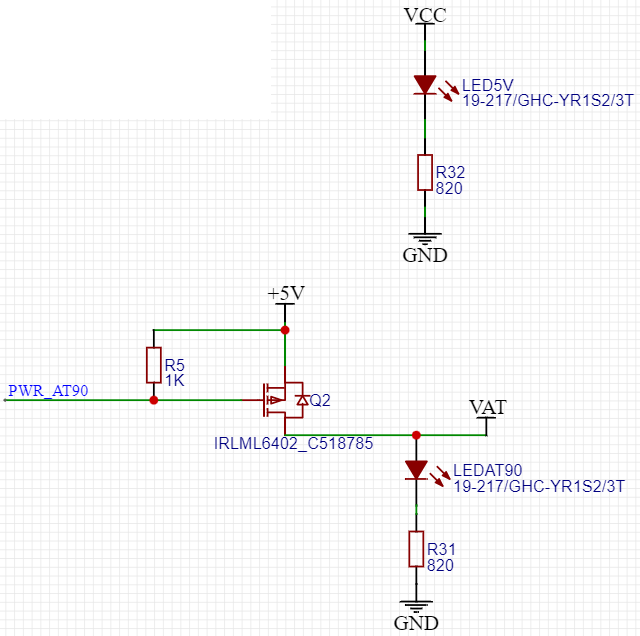
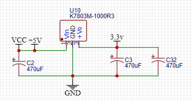
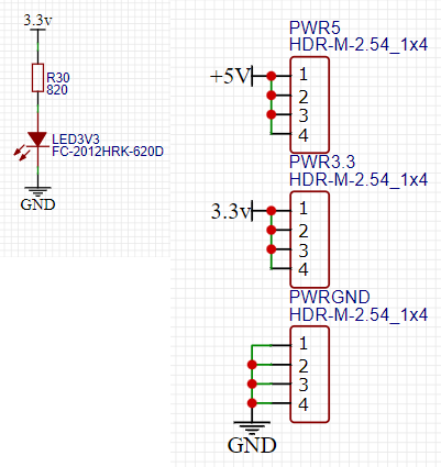
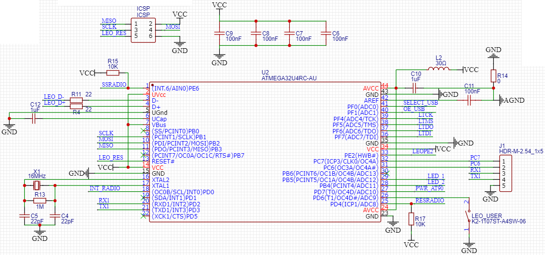
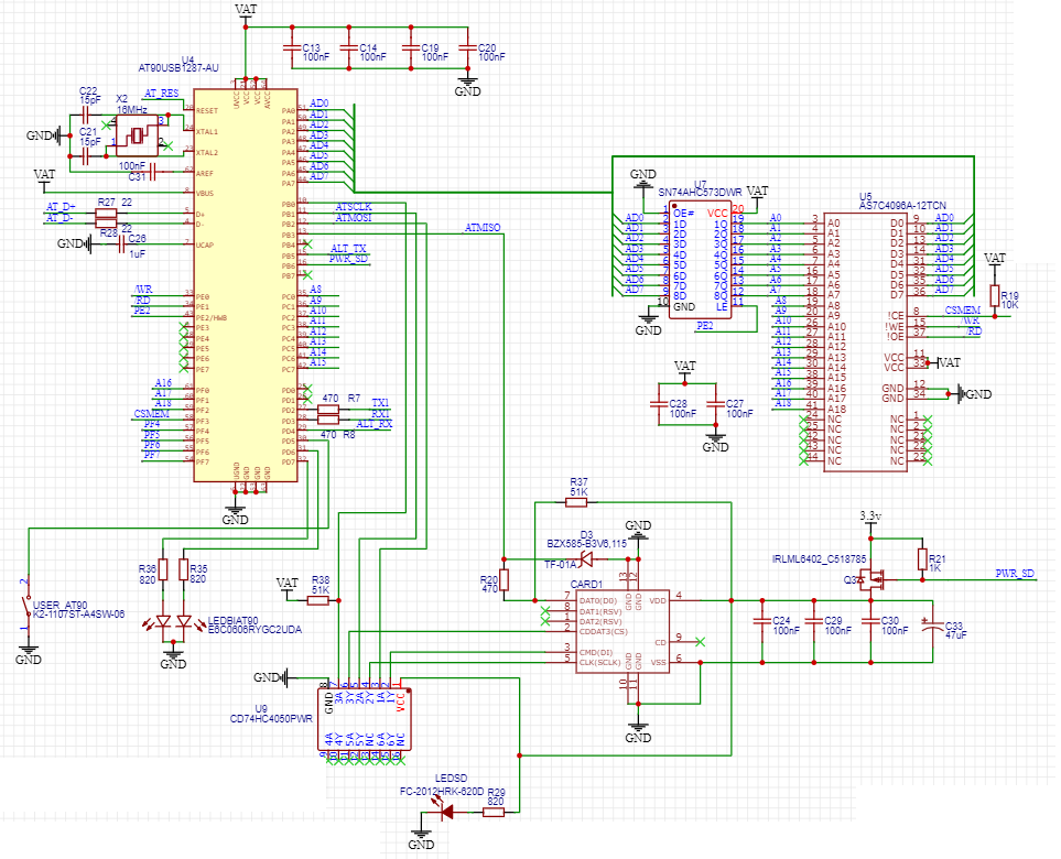
schematics (MIT LICENSE)
rpk2 v3
USB SWITCH + POWER
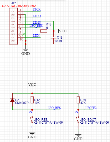
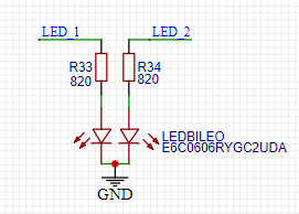
LEO
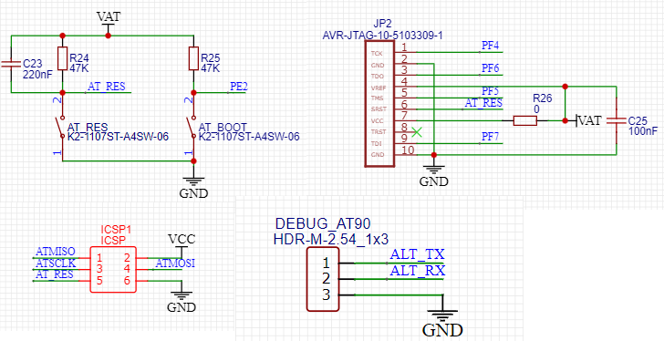
AT90
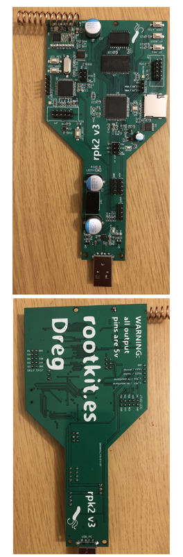
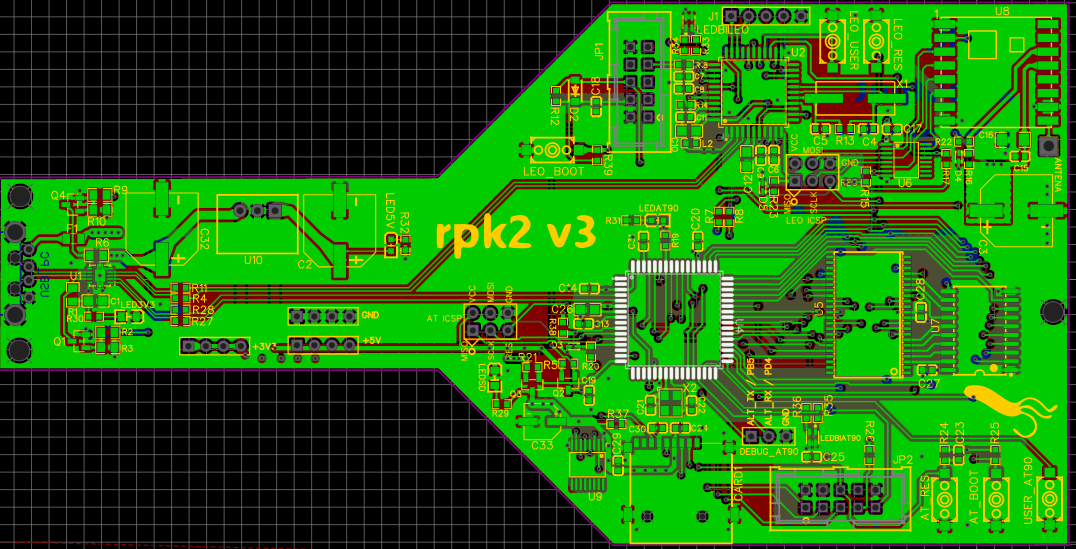
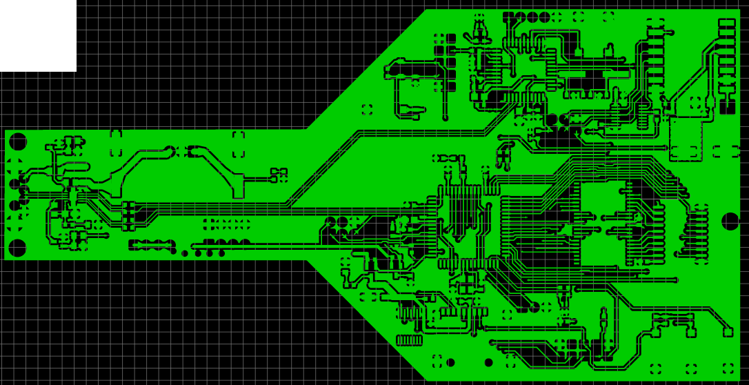
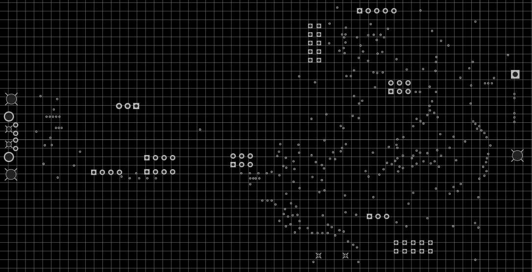
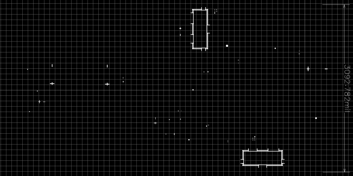
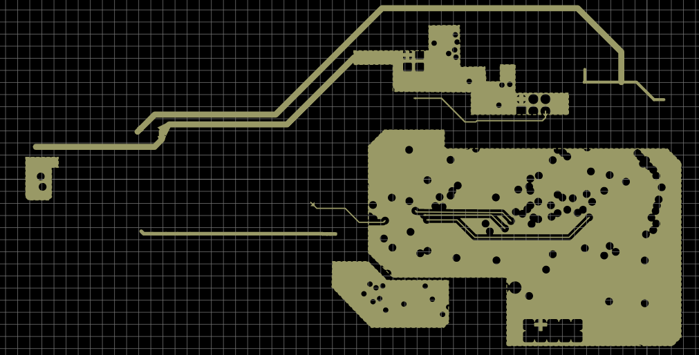
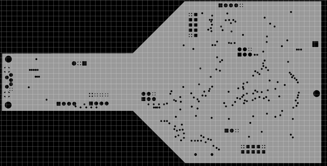
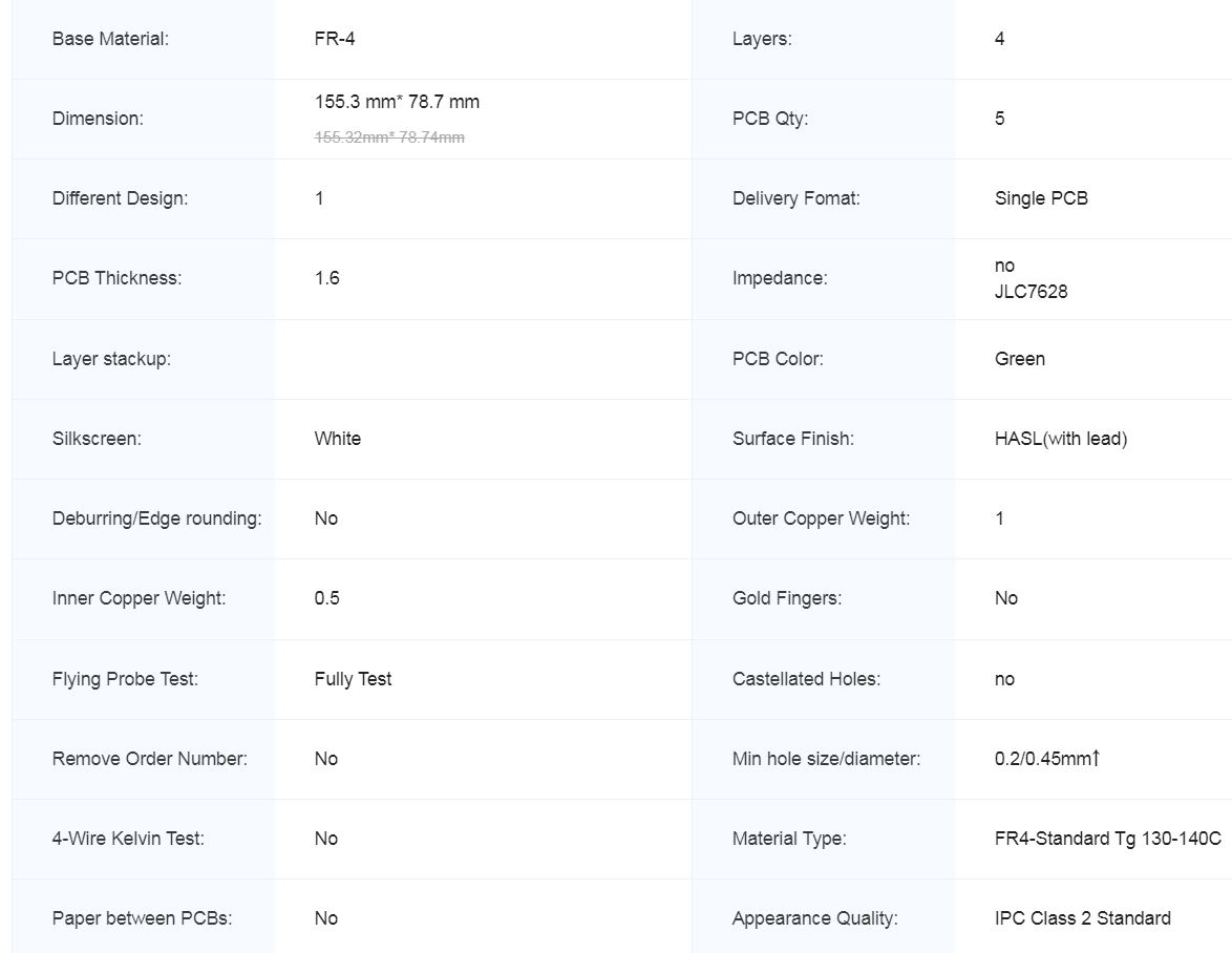
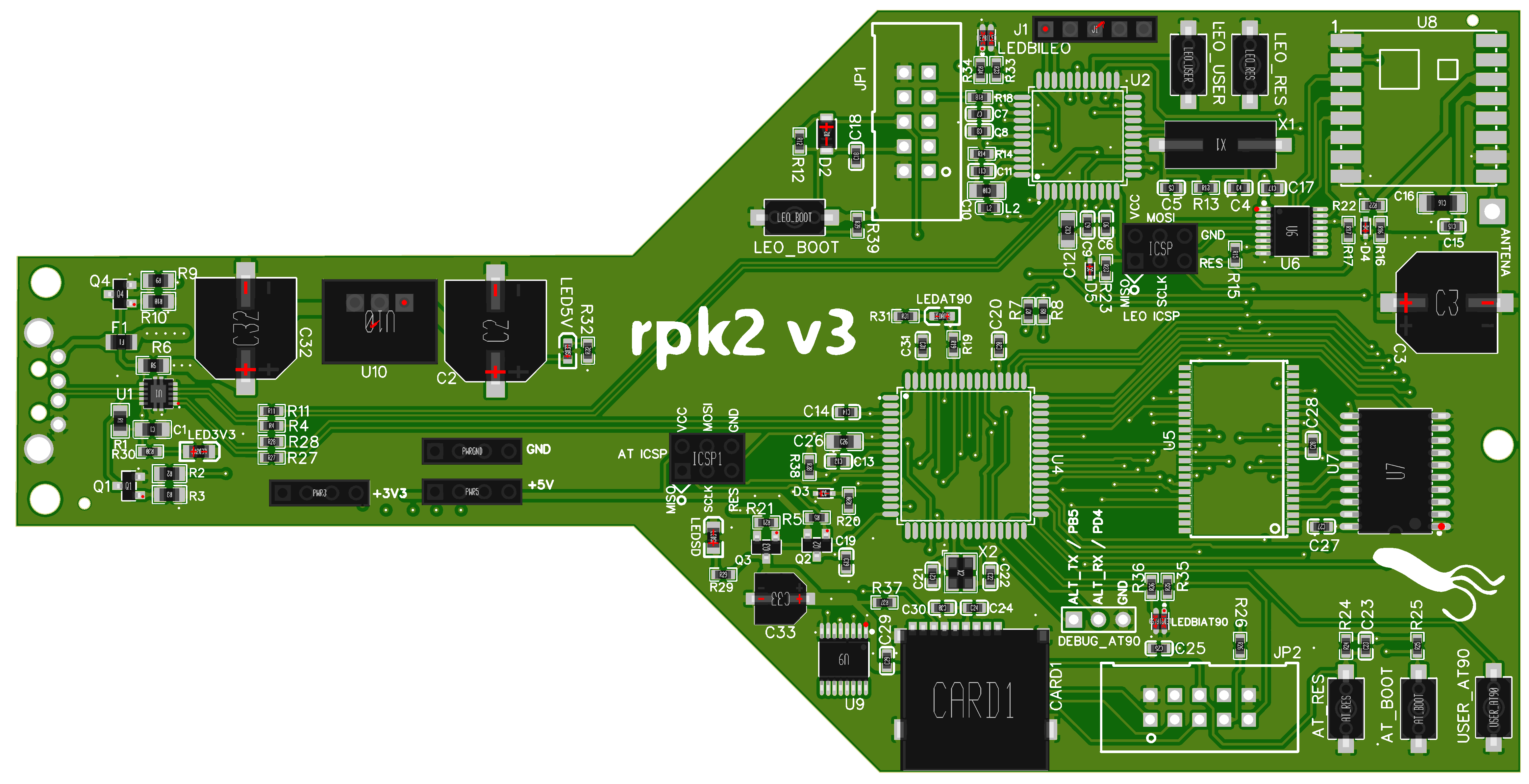
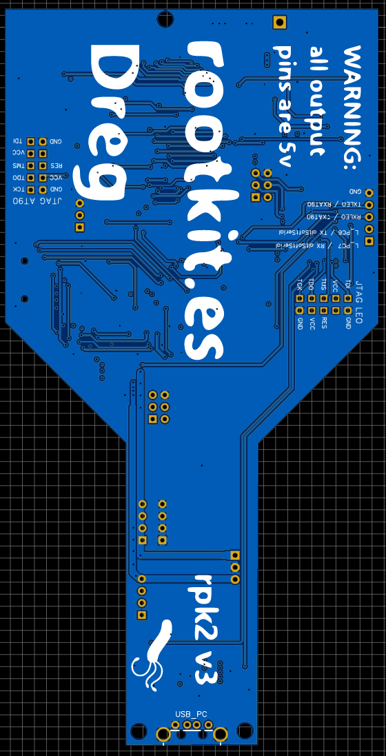
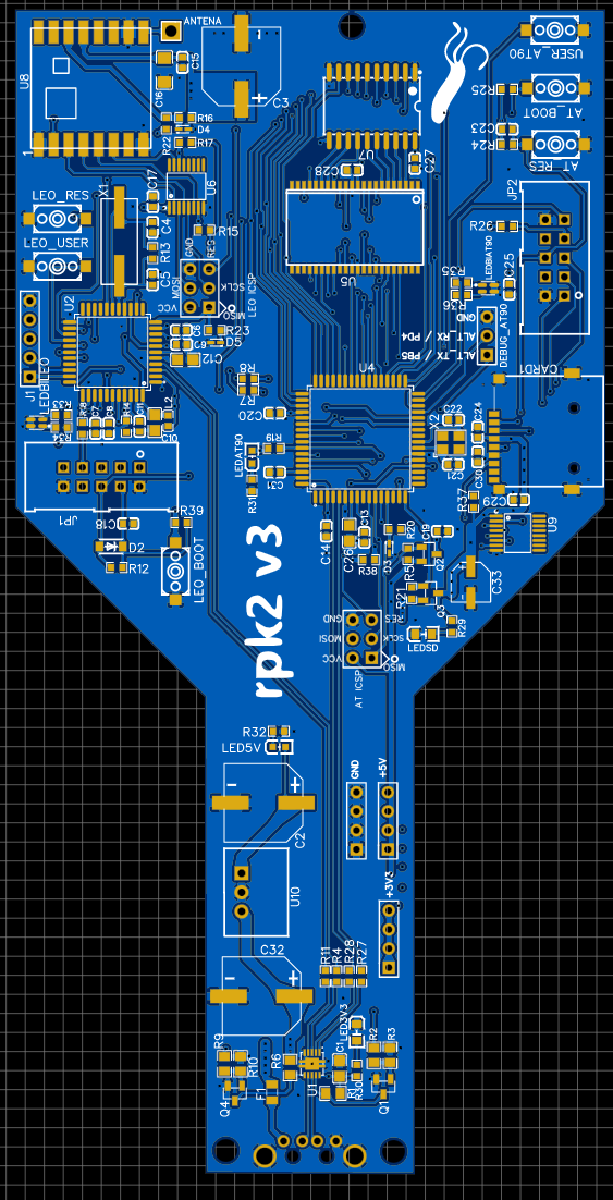
PCB (MIT LICENSE)
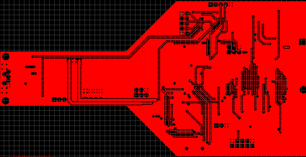
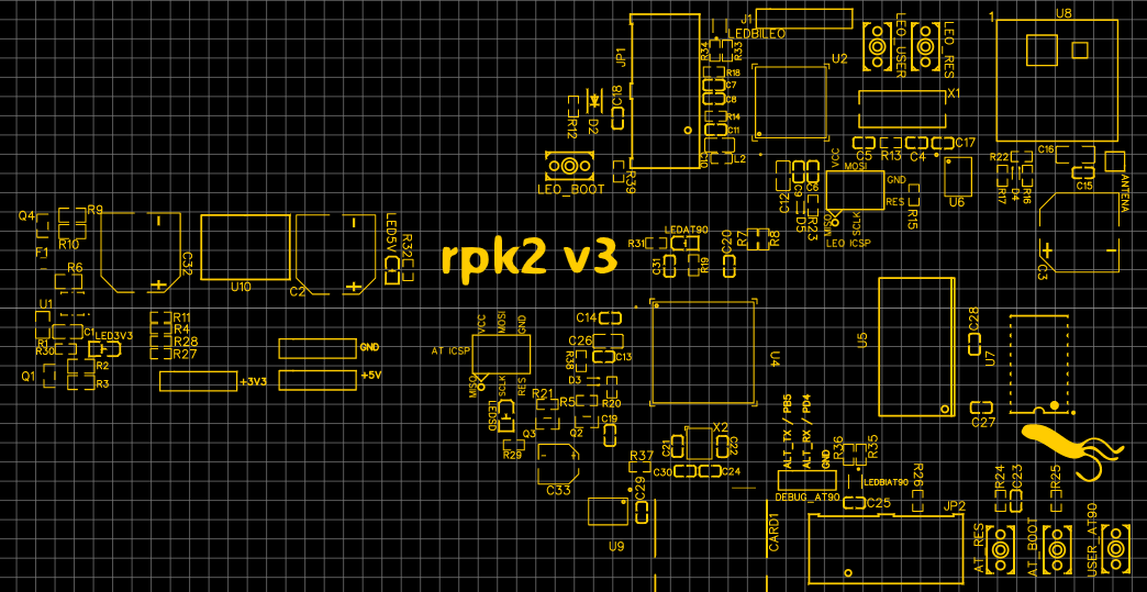

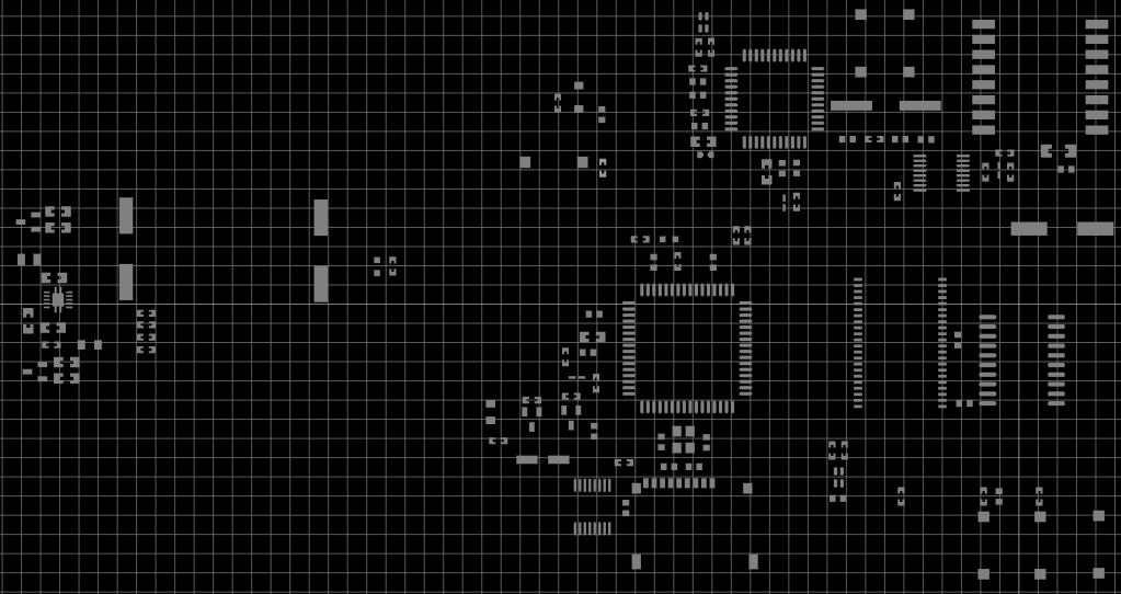
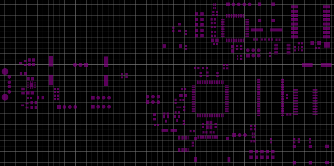

BOM
ID	Name	Designator	Footprint	Quantity	Manufacturer Part	Manufacturer	Supplier	Supplier Part	Price
1	U-USBAR04P-M002	USB_PC	USB-A-TH_U-USBAR04P-M002	1	U-USBAR04P-M002	Shenzhen Cankemeng	LCSC	C386753	0.082
2	HDR-M-2.54_1x3	DEBUG_AT90	HDR-M-2.54_1X3	1			LCSC	C180248	0.236
3	HDR-M-2.54_1x5	J1	HDR-M-2.54_1X5	1			LCSC	C358687	0.022
4	AT90USB1287-AU	U4	TQFP-64_L14.0-W14.0-P0.80-LS14.0-BL	1	AT90USB1287-AU	MICROCHIP(美国微芯)	LCSC	C1337397	14.2
5	47uF	C33	CAP-SMD_BD5.0-L5.3-W5.3-FD	1	OVZ470M1A0506-TRO	Lelon	LCSC	C250111	0.183
6	HDR-M-2.54_1x4	"PWR3,PWR5,PWRGND"	HDR-M-2.54_1X4	3			LCSC	C124378	0.028
7	ICSP	"ICSP1,ICSP"	HDR-M-2.54_2X3	2			LCSC	C132438	0.15
8	K2-1107ST-A4SW-06	"LEO_BOOT,AT_BOOT,AT_RES,LEO_RES,LEO_USER,USER_AT90"	KEY-SMD_L6.2-W3.6-LS8.0	6	K2-1107ST-A4SW-06	Rectangular Connectors - Contacts	LCSC	C118141	0.056
9	47K	"R39,R24,R25"	R0603	3	0603WAF4702T5E	UniOhm	LCSC	C25819	0.001
10	FC-2012HRK-620D	"LED3V3,LEDSD"	LED0805-RD_RED	2	FC-2012HRK-620D	NATIONSTAR	LCSC	C84256	0.012
11	19-217/GHC-YR1S2/3T	"LED5V,LEDAT90"	LED0603-R-RD	2	19-217/GHC-YR1S2/3T	EVERLIGHT	LCSC	C72043	0.027
12	E6C0606RYGC2UDA	"LEDBIAT90,LEDBILEO"	LED-SMD_4P-L1.6-W1.6-BL-RD	2	E6C0606RYGC2UDA	EKINGLUX	LCSC	C375543	0.036
13	51K	"R38,R37"	R0603	2	0603WAF5102T5E	UniOhm	LCSC	C23196	0.001
14	16MHz	X2	OSC-SMD_4P-L3.2-W2.5-BL	1	X322516MLB4SI	YXC	LCSC	C13738	0.084
15	1K	"R5,R21"	R0603	2	0603WAF1001T5E	UniOhm	LCSC	C21190	0.001
16	15pF	"C21,C22"	C0603	2	CL10C150JB8NNNC	SAMSUNG	LCSC	C1644	0.006
17	ATMEGA32U4-AU	U2	TQFP-44_L10.0-W10.0-P0.80-LS12.0-BL	1	ATMEGA32U4-AU	MICROCHIP(美国微芯)	LCSC	C44854	7.026
18	HDR-M-2.54_1x1	ANTENA	HDR-M-2.54_1X1	1	712-ANT-433-HETH	Linx Technologies	Mouser	712-ANT-433-HETH	1.8
19	BSMD0805-035-24V	F1	FUSE-SMD_L2.1-W1.4-1	1			LCSC	C910821	0.053
20	470uF	"C32,C3,C2"	CAP-SMD_BD10.0-L10.3-W10.3-RD	3	OVZ471M1A1008-TRO	Lelon	LCSC	C250114	0.28
21	SN74AHC573DWR	U7	SOP-20_L12.8-W7.5-P1.27-LS10.4-BL	1	SN74AHC573DWR	TI	LCSC	C58204	0.245
22	1uF	"C1,C10,C12,C26"	C0805	4	CL21B105KBFNNNE	SAMSUNG	LCSC	C28323	0.01
23	22pF	"C4,C5"	C0603	2	CL10C220JB8NNNC	SAMSUNG	LCSC	C1653	0.004
24	100nF	"C6,C7,C8,C9,C11,C13,C14,C15,C17,C18,C19,C20,C24,C25,C27,C28,C29,C30,C31"	C0603	19	CC0603KRX7R9BB104	YAGEO	LCSC	C14663	0.002
25	10uF	C16	C1206	1	CL31A106KBHNNNE	SAMSUNG	LCSC	C13585	0.033
26	220nF	C23	C0603	1	CL10B224KA8NNNC	SAMSUNG	LCSC	C21120	0.006
27	TF-01A	CARD1	TF-SMD_TF-01A	1	TF-01A	HRO	LCSC	C91145	0.167
28	SM4007PL	D2	SOD-123F_L2.8-W1.8-LS3.7-RD	1	SM4007PL	MDD	LCSC	C64898	0.008
29	"BZX585-B3V6,115"	"D3,D4,D5"	SOD-523_L1.2-W0.8-LS1.6-RD	3	"BZX585-B3V6,115"	Nexperia	LCSC	C455026	0.042
30	AVR-JTAG-10-5103309-1	"JP1,JP2"	HDR-5103309-1	2			LCSC	C5665	0.06
31	30Ω	L2	L0603	1	PBY160808T-300Y-N	Chilisin	LCSC	C142075	0.004
32	MMBT2222A_C916372	"Q1,Q4"	SOT-23-3_L2.9-W1.3-P1.90-LS2.4-BR	2	MMBT2222A	JSMSEMI	LCSC	C916372	0.01
33	IRLML6402_C518785	"Q2,Q3"	SOT-23-3_L2.9-W1.3-P1.90-LS2.4-BR	2	IRLML6402	HUASHUO	LCSC	C518785	0.054
34	1K	"R1,R6"	R0805	2	0805W8F1001T5E	UniOhm	LCSC	C17513	0.002
35	3.3K	"R2,R9"	R0805	2	0805W8F3301T5E	UniOhm	LCSC	C26010	0.002
36	10K	"R3,R10"	R0805	2	ERJ6ENF1002V	PANASONIC	LCSC	C169253	0.008
37	22	"R4,R11,R27,R28"	R0603	4	0603WAF220JT5E	UniOhm	LCSC	C23345	0.001
38	470	"R7,R8,R20,R22,R23"	R0603	5	0603WAF4700T5E	UniOhm	LCSC	C23179	0.001
39	10K	"R12,R15,R16,R17,R19"	R0603	5	0603WAF1002T5E	UniOhm	LCSC	C25804	0.001
40	1M	R13	R0603	1	0603WAF1004T5E	UniOhm	LCSC	C22935	0.001
41	0	"R14,R18,R26"	R0603	3	0603WAF0000T5E	UniOhm	LCSC	C21189	0.001
42	820	"R29,R30,R31,R32,R33,R34,R35,R36"	R0603	8	0603WAF8200T5E	UniOhm	LCSC	C23253	0.001
43	TS3USB221DRCR	U1	VSON-10_L3.0-W3.0-P0.50-TL-EP_TPS62410DRCR	1	TS3USB221DRCR	Texas Instruments	LCSC	C324071	1.038
44	AS7C4096A-12TCN	U5	TSOP44-II	1	AS7C4096A-12TCN	Alliance Memory	LCSC	C1348896	6.6
45	CD74HC4050PWR	"U6,U9"	TSSOP-16_L5.0-W4.4-P0.65-LS6.4-BL	2	CD74HC4050PWR	Texas Instruments	LCSC	C352825	0.29
46	RFM69HCW	U8	RFM69HCW-XXXS2	1	RFM69HCW	hoperf	Mouser	474-COM-13910	5.21
47	16MHz	X1	HC-49S_L11.4-W4.8	1	X49SM16MSD2SC	YXC	LCSC	C12676	0.073
48	K7803M-1000R3	U10	PWRM-TH_K78XXM-1000R3	1	K7803M-1000R3	MORNSUN	LCSC	C132363	3.695